Diversified Electronics Special Controls
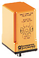
SPM-120-AAA
|
The seal failure module is a specialized
control for monitoring the shaft seal of a submersible pump motor. A
leak is detected by sensing the position of a resistive float switch
installed in the seal cavity. When the resistance drops below the
sensitivity rating, the output relay energizes and the LED illuminates.
When the fault condition clears, the output relay resets automatically.
Back to top |
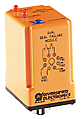
SPM-120-ABA
|
The dual seal failure module is a specialized
control for monitoring the shaft seals of two submersible pump motors.
Leaks are detected by sensing the conductivity of the contaminating
fluid through probes installed in the seal cavity. When a seal begins to
leak, the seal failure module energizes one of its SPST output relays
indicating that the seal needs to be replaced before the motor is
damaged. The sensitivity of the probe inputs is field adjustable. When
the resistance between one of the probe inputs and the common connection
drops below the sensitivity setting, the corresponding output relay and
LED are activated.
Back to top |
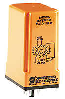
SPM-120-ACA/-ADA
|
The nonvolatile latching temperature switch
relay monitors a normally-closed-low temperature switch. It incorporates
a bistable relay that retains its state during power failures. LEDs
indicate the status of the relay, and connections for an external reset
button are provided for manual control. The reset inputs of multiple
units may be connected to a single push button as long as proper
polarity is observed when making the connections. Under normal
conditions the temperature switch is closed and the relay is
de-energized. When the temperature switch opens, the relay energizes and
latches on until the temperature switch recloses and the reset button is
pressed. The unit will function properly with zero to 2 k ohm of
resistance in series with the temperature switch.
Back to top |
SPM-120-AEE
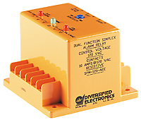
|
The dual function simplex alarm/relay is a
specialized control for monitoring the shaft seal and stator temperature
of a submersible pump motor. Seal leakage is detected by either a
resistive float switch or a pair of conductive probes installed in the
seal cavity. Over-temperature is detected by a normally-closed-low
temperature switch mounted on the stator. The over-temperature function
incorporates a bistable relay that retains its position during power
failures.
Back to top |
PRT-100
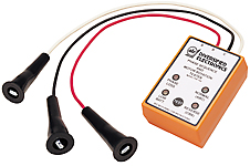
|
The PRT-100 is a handheld tester that takes
the guesswork out of connecting a three-phrase motor. The direction of
rotation of a motor depends on phase sequence of the power line
connections. If the sequence is reversed, the motor will run in the
wrong direction, possibly damaging the equipment connected to the motor.
The PRT-100 identifies the leads of a three-phase motor and detects the
sequence of a three-phase power line. Once the motor and line leads are
properly identified, the motor can be wired so that it turns in the
desired direction on the first try. The unit also detects phase loss and
no voltage conditions.
Back to top |
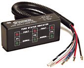
GFD Series
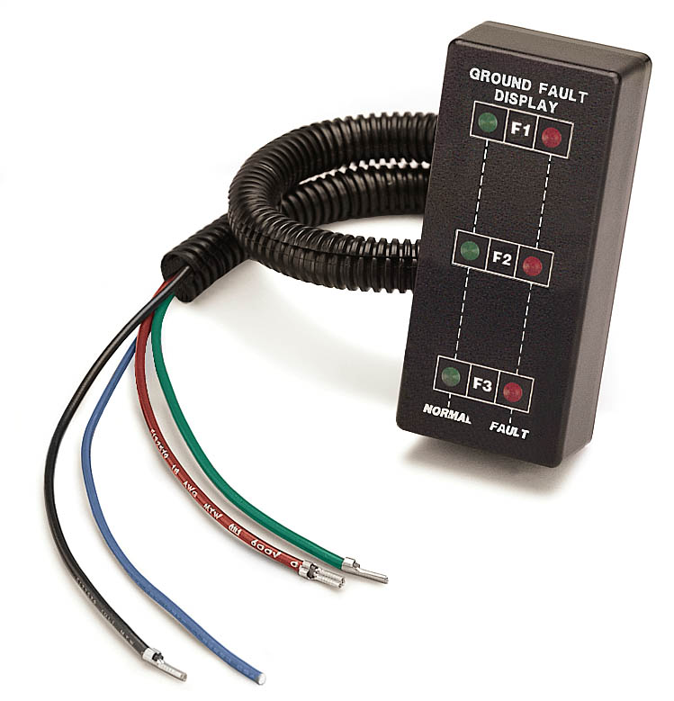
|
The GFD-XXX is intended for the use on
ungrounded systems to detect and indicate the phase of the first ground
fault condition. This enables corrective action to avoid the potential
hazards resulting from a second ground fault. With nominal 3 phase line
voltage applied, a flashing NORMAL green LED gives indication of a
non-fault condition and integrity of the wire connection to the
corresponding phase.
A Flashing red LED gives positive FAULT indication of either a
phase-to-ground fault, or a lost connection to the corresponding phase.
Back to top |
UPA-100 Series
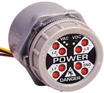
UL Approved
CSA Approved
|
With the green (GND) wire connected to earth
ground, the eight detector UPA-100 visually alerts to the presence of
dangerous AC or DC (Stored Energy) potentials occurring between any
combination of the four monitored input lines (L1, L2, L3, GND). Two LED
indicators are assigned to each input line and are designated "+" and
"-". For each input line carrying an AC potential (bipolar), both the
"+" and "-" LEDs will be active. A DC or Stored Energy potential will
illuminate the "+" LED for the positive line and the "-" LED for the
negative line.
OSHA 1910.147 THE CONTROL OF HAZARDOUS ENERGY
(Lockout/Tagout).
Following the application of lockout or tagout devices to energy
isolating devices, all potentially hazardous stored or residual energy
shall be relieved, disconnected, restrained, and otherwise rendered
safe.
(d)(5)(ii)
If there is a possibility of reaccumulation of stored energy to a
hazardous level, verification of isolation shall be continued until the
servicing or maintenance is completed, or until the possibility of such
accumulation no longer exists.
(d)(6)
"Verification of Isolation." Prior to starting work on machines or
equipment that have been locked out or tagged out, the authorized
employee shall verify that isolation and de-enegerization of the machine
or equipment have been accomplished.
Back to top |
SP-0313
MotoReset
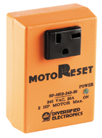
|
When the voltage to your equipment is lost
due to tripped breakers, blown fuses, or loss of utility power. Simply
remove the existing cord set plug from the outlet, plug into the
properly sized MotoReset device, and plug the assembly back into the
outlet. The unsupervised unintentional automatic restart of equipment
when breakers are reset or when utility power is restored after an
outage. Restoration of utilities with equipment control switches left in
the “ON” position will not restart with the MotoReset in place. The need
for additional, potentially hazardous, manual reset pushbuttons. The
MotoReset turns the equipment existing ON/OFF switch into a manual reset
switch. The operator does not have to leave the immediate vicinity, nor
the normal operating position of protected equipment, to safely reset
after an outage. Simply switch the equipment “OFF” to reset to normal
operation.
Back to top |
CCT Series
|
The CCT Series, Crank Cycle Timer, provides a
sequential Crank/Reset signal for starting commercial and industrial
portable, standby, and emergency power generators. When the supply
voltage is applied to the input terminals, Load #1 energizes and the
Crank Time (t1) begins. Upon completion, Load #1 de-energizes and the
rest time (t2) begins. Upon completion, Load #1 energizes. This
Crank/Rest action continues for a preselected number of cycles, where
upon completion, Load #1 locks in a de-energized state and Load #2
energizes. Reset is accomplished by interrupting the supply voltage.
PLEASE NOTE: This timer has been
obsoleted by ATC/Diversified. Please contact us at 800-479-4783
regarding a low-cost PLC replacement offering.
 |
Low Cost |
|
Adjustable Crank/Reset Delay |
|
CMOS Technology |
|
Totally Solid State Circuitry |
|
Selective Number Of Cycles |
Back to top
|
|
|